Table of Contents
T3100 | T3100e | T3100SX | T3200 | T3200SX | T3200SXC | T5200 | T5200C
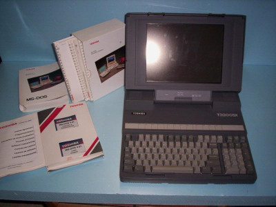
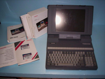
Toshiba T3200SX
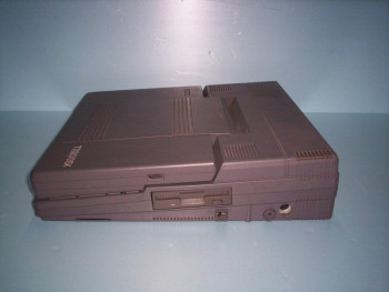
A durable workhorse of it's time, the T3200SX and T3200SXC portable computers were manufactured and targeted primarily as desktop replacement computer for businesses. Of course, at the time of the release, there existed smaller laptop computers, but none of these even came close to the power, durability and expandability of this Toshiba computer.
The T3200SX and T3200SXC are siblings. The only major differences are that the SXC has a color flat panel screen and a faster CPU (20 MHz as opposed to 16 MHz). The graphics adapters are the same, both systems are VGA capable, and support resolutions up to 640×480 with 16 colors.
| Technical Specifications | |
|---|---|
| Year Announced | 1989 |
| Processor | 16MHz Intel 80386SX-16 |
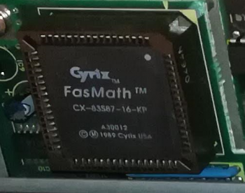
| Coprocessor | Optional 80387SX-16 math co-processor, such as Cyrix CX-83S87-16-KP |
| RAM | Standard 1 MB of RAM, expandable up to 13 MB. |
| Hard disk | T3200SX comes standard with a Conner CP-model IDE hard disk, either 40 MB or 80 MB (BIOS selectable) T3200SX/120 comes standard with a Conner 120 MB IDE hard disk. |
| Floppy disk | 3,5“ 1.44 MB High Density (HD) diskette drive |
| Video Adapter | VGA compatible WD 90C21 chip with 256 KB video RAM with VGA output. |
| Internal display | 11.2” flat panel orange/amber plasma display with 640 by 480 native resolution and 16-level gray scale. |
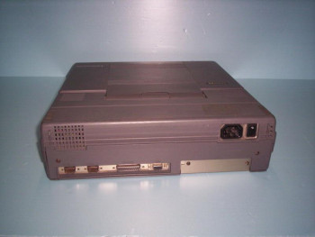
| I/O Ports | 1x VGA, 1x Parallel, 2x RS232C Serial, 1x DIN keyboard connector. |
| Internal expansion slots | 1x full size 16/8-bit ISA slot 1x half-size 8-bit ISA slot |
| Power Supply | Universal. Works with 110V/220V and 50/60 Hz power. |
| Dimensions | 370 x 395 x 99 mm (W x D x H) |
| Weight | 7.9 kg (17.4 lbs) |
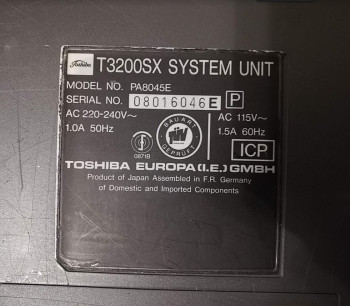
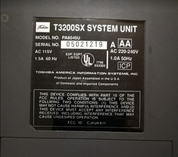
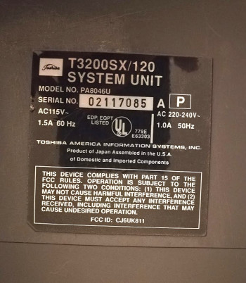
| Known model numbers | T3200SX (EU): PA8045E T3200SX (US): PA8045U T3200SX/120 (US): PA8046U |
| Other features | |
| Software | |
|---|---|
| Operating System | Toshiba MS-DOS 4.01 Toshiba MS-DOS 3.3 OS/2 1.1 T/PIX 2.1 (AT&T UNIX System V/386 R3.0 (option) |
System Boot process
System Upgrades
Hard disk
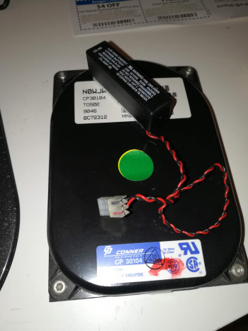
Toshiba T3200SX comes with either a 40 MB or a 80 MB hard drive. As far as I understand, there was also a T3200SX/120 which was a upgraded model, and comes with a 120 MB hard disk. The system has a standard IDE interface to connect to the supplied Conner CP hard disk.
These are the drive configurations supported by standard T3200SX BIOSes:
| Model | Native C/H/S1) | BIOS reported C/H/S2) | Capacity | Seek time | ||||||||
|---|---|---|---|---|---|---|---|---|---|---|---|---|
| C | H | S | C | H | S | MiB | MB | |||||
| Conner CP-30003) | 1045 | 2 | 40 | 862 | 2 | 48 | 40 MB | 43 MB | 28 ms | |||
| 695 | 7 | 17 | ||||||||||
| Conner CP-30444) | 1047 | 2 | 40 | 980 | 5 | 17 | 40 MB | 43 MB | 25 ms | |||
| Conner CP-xxxx | | | | 981 | 10 | 17 | 81 MB | 85 MB | Unknown | |||
| 695 | 14 | 17 | 80 MB | 85 MB | ||||||||
| 862 | 4 | 48 | 80 MB | 85 MB | ||||||||
These configurations are supported by T3200SX/120 (with at least the 003F BIOS):
| Model | Native C/H/S5) | BIOS translated C/H/S6) | Capacity | Seek time | ||||||||
|---|---|---|---|---|---|---|---|---|---|---|---|---|
| C | H | S | C | H | S | MiB | MB | |||||
| Conner CP-30447) | 1047 | 2 | 40 | 980 | 5 | 17 | 40 MB | 43 MB | 25 ms | |||
| Conner CP-301048) 9) | 1524 | 4 | 39 | 762 | 8 | 39 | 120 MB | 122 MB | 19 ms | |||
Search these hard drives on eBay 10)
I'm missing the part number of the 80 MB Conner hard disk. If you know it, please let me know!
This system can be expanded with an 8-bit and 16-bit ISA expansion cards. Hence, you can purchase an XT-IDE adapter to add a hard drive, such as the XT-CF-MINI or XT-CF-Lite card to add a Compact Flash card as a hard drive. They usually run for $40-$60. You can find them on eBay or Texelec.
Another option is to purchase an XT-IDE adapter for the Toshiba proprietary expansion slot. There is a maker on eBay that sells Toshiba type expansion cards with XT-IDE to allow many different types of IDE and CF cards to be used on the portable computer. Please see the following link for the sales article. 3inONEder: Toshiba Portables
Audio and ethernet
The same adapter that allows you to use the Toshiba proprietary slot connector for XT-IDE and custom hard disks also optionally allows to add audio (Adlib) and ethernet support (partially NE2000 compatible). Please see the following link for the sales article. 3inONEder: Toshiba Portables
CPU upgrades and overclocking
I've been informed that it is possible to replace the CPU with a TX486SLC upgrade, however this will require soldering. Credits for this discovery go to mohhingman. Thank you!
RAM memory upgrade
The computer uses 30 pin SIMM modules to add more system memory, but as far as I know they are proprietary Toshiba specific modules. The computer was shipped with 1 Mb (megabit) or 2Mb memory chips that were 80ns (or faster) and have parity. There are six slots in total and the banks are used in pairs, so at least two are needed. Standard configuration comes with 2 MB of RAM preinstalled, upgrade models come with 4 MB. The memory is upgradable up to 13 MB 11)
ISA Expansion Slots
If you remove the rear panel, you will be able to access the ISA expansion slots. The computer has one 16-bit full-length ISA slot and one 8-bit half-length ISA slot. The system also has a proprietary 16-bit Toshiba expansion slot. I have my computer set up with an 16-bit Sound Blaster 16 and an 8-bit 3Com Etherlink III (3C509) for networking. However, at least this site 12) points out, that not all newer 3Com Etherlink III cards support 8-bit ISA.
Math coprocessor (FPU)
The computer can be upgraded with an math coprocessor (FPU). The FPU doesn't come as standard, but the computer has a provision for an added Intel or compatible 387 FPU. One computer that I repaired had the Cyrix CX-83S87-16-KP FPU installed.
AT keyboard connector
The computer has a DIN connector for a AT style keyboard but it may be covered by a plastic cap. Please see the DIN keyboard connector page for more information.
CMOS clock battery
Lithium 3.6V battery supplied. A T3200SX/120 I had came with an original Tadiran TL-5207 3.6V battery. It had a plastic container package, that actually just contained a Tadiran TL-5151 3.6V 1/2 AA lithium battery. Please see gallery for more pictures.
Frequently Asked Questions
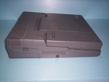
Q: What is the PRN-A-B Switch on the side?
A: Toshiba offered an external 360Kb disk drive as an option. This plugs in to the parallel port connector but is not a parallel device. Setting the switch to PRN enables the printer port, setting it to A tells the machine there is an external disk drive and you want it to be A drive. Setting it to B tells the machine there is an external disk drive and you want it to be B drive. Setting it to A would allow you to boot 360Kb boot disks.
Unless you have the Toshiba external floppy – always set this to PRN. 13)
System Maintenance
BIOS clock battery replacement
The BIOS battery header is located on the system board. The battery is traditionally tucked in at the back of the floppy drive. The correct voltage for the battery is 3.6V. To replace the battery, do the following:
Remove the old battery by cutting the leads at the battery terminals, and get a replacement battery ER14505 3.6V lithium, sold new at eBay and other sources. You will also need a 1x AA battery holder. If you cut the leads at the battery terminals, you should have been able to preserve the in line 330 ohm resistor at the negative pole and you will want to leave that in place. Solder the old battery wire to the battery holder and place it where the old battery was, right behind the floppy drive. Alternatively, you can use any 14500 3.6V lithium battery as the clock battery. In any case, your setup will look something like this:
[BATT +]----------[+ ER14505 -]---------.
[BATT -]-------------[ 330R ]-----------'
Hard Disk upgrade
The upgrade method depends on the BIOS version of your Toshiba portable (see below for instructions how to check the BIOS version). Most Toshiba T3200SX BIOSes are restricted to CONNER hard-drives of either 40 or 80 megabytes size (T3200SXC will be either 40 or 120 MB). On boot-up, the BIOS queries the IDE controller for hard-drives, and depending on your BIOS version, one of two things will happen:
- Older Toshiba BIOS (such as 003C)
- The computer will detect any drive and just assume it's a 40 MB disk (regardless of its actual size).
- New Toshiba BIOS (such as 003E-003I)
- The computer will not boot an unsupported drive unless it is manufactured by Conner. It will assume it's a 40 MB drive (regardless of its actual size). If you have a different drive than Conner, the computer will simply refuse to boot from the hard disk. The model/part number reported to the computer must match the letters 'CP' (Conner Peripherals) for it to be detected.
You have a couple of options:
- If the computer has the older BIOS such as the 003C, the computer should ignore the part number and will attempt to boot the hard disk regardless, even with incorrect settings. However, since the settings are fixed, you can not use more than the amount of space specified in the BIOS, which is only 40 MB. To override the BIOS limitation and use more space on the disk, so you will need to manually correct the settings on boot using a drive overlay software which is installed on the hard disk. I have tested a program called Anydrive, and I believe Western Digital's EZ-Drive version 9.03W will work as well. Both programs can be found in the files section. Anydrive overrides the BIOS settings so you can use any size hard disk (or CF memory card with CF to IDE adapter) up to 504 MB. With EZ-Drive you can potentially use larger disks, but run the risk of disk file corruption above 4 GB.
- If you have the newer BIOS, you can do the following:
- Buy a BIOS ROM chip drop-in replacement. Please see my Replacement BIOS ROM chips section for more information how to buy.
- Buy a compatible Conner hard-disk. The compatible part numbers are listed above.
- If you have an EEPROM programmer, such as the Minipro TL866, you can make your own BIOS chip and replace the problematic one by using HighTreason's excellent tutorial. Programming a compatible BIOS will allow you to boot with any hard disk, and then simply install a hard disk overlay program to override the drive parameters with correct ones. The tutorial, associated ROM images and HDD overlay programs are in the Files and Resources page.
- You can also buy an XT-IDE adapter, such as the XT-CF-lite from Lo-Tech. TexElec carries these in stock in the US. This will bypass the built-in IDE controller completely and replace it with a CF card. You can then set your BIOS to “No drive”.
Note: If you plan to use a drive other than what was supplied with your computer, you must use a BIOS HDD overlay program (in the files and resources section) to avoid data corruption.
Q: I upgraded the hard disk on my Toshiba, but now it refuses to boot, or doesn't detect the hard disk.
A: If you have verified the replacement disk is fully working, then your computer must be using a BIOS version that only detects and supports Conner hard disks. See above for details.
Check the BIOS version
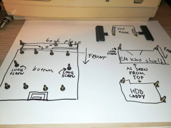
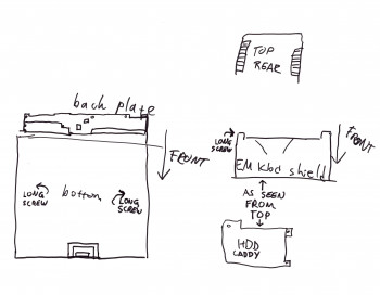
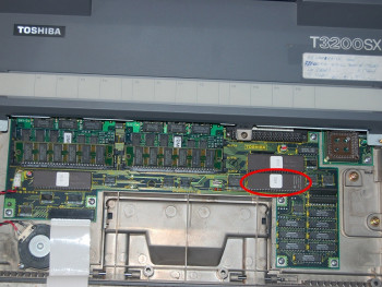
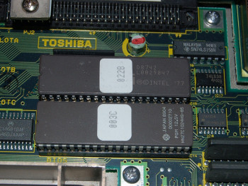
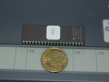
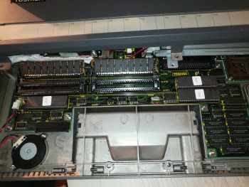
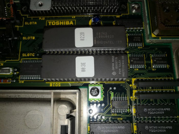
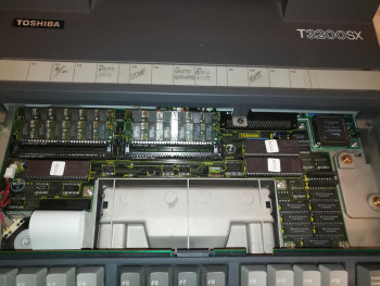
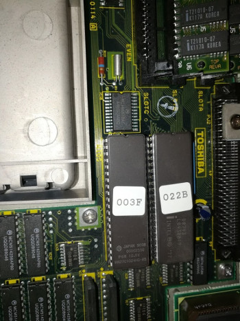
You need to open the portable computer. Remove the four screws from the bottom front of the laptop. Open the screen lid. The keyboard should now lift up starting from the front. You may need to pry the keyboard a little. Once the keyboard is off, remove two screws at the rear of the EM shield between the keyboard and the motherboard. Remove the EM shield. You will see three chips. The one at the bottom right corner is the BIOS chip. So far I've seen 003C, 003E, 003F, 003H and 003I out in the wild. If you have a different BIOS version, please take a picture of it and send a BIOS dump over. I will be happy to host it on this site.
Moving the display out of the way to access PSU, HDD, FDD
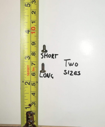
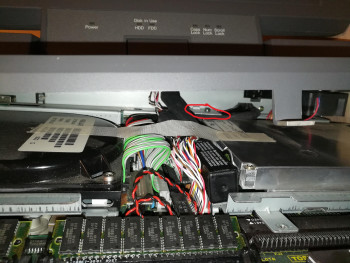
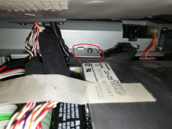
After opening the laptop, you will find that getting access to other components toward the rear of the system can be tricky, especially to access the hard drive, floppy drive or the power supply unit. If your laptop has never been opened, chances are there is a metal piece fastened to the chassis that will prevent you from pulling the flat panel free as it is holding the flat panel cables down. The latch will be held on by a single screw. You will need a short Philips screw driver with preferably a 90 degree angle at the bit to unscrew the piece and release the flat panel display cable.
If you don't have access to a small angled screw driver, you may be able to bend the latch up and out of the way to release the display cable and extend access to the back of the system. It is risky as you may damage the display cable near the latch so please be careful. Never pull or twist on the display cable, and always support the display while it is on its side.
To access the rear half of the system, I have found this arrangement to provide ample access.
Accessing the internals of the display panel
The display panel front bezel is fastened by four screws. Two on the top corners of the display bezel (under rubber bumpers), and two screws under the sticker that covers the power, HDD, FDD and keyboard LEDs. The screws are close to the outer edges of the sticker, so you should be able to use a flat shimmy or a dull but flat knife to carefully separate it just enough to access the screws. You don't need to remove the whole sticker, just enough to reveal the two screws. I've done this to both my T3200SX's, and there is almost no damage if you do it right. Do not pull or bend the sticker at any time to avoid bending or damaging it. Just slip the shimmy under it and push the shimmy toward the middle so it separates.
In this video you can see the process. Doing it one handed while taking video, the shimmy slipped, but I hope you get the idea. Also, the tool I'm using is iFixit Jimmy
Once you remove all four screws, the bezel is ready to come off. Open the display lid all the way, and pull on the bezel from the bottom. The bezel should easily separate allowing you to access the rest of the display assembly.
Removing the entire top cover of the computer
The top cover cannot be removed until the display panel is disconnected. It can only be disconnected from the display panel itself, so you'll need to first open up, disconnect and remove the panel. To remove the panel, first follow instructions under “Accessing the internals of the display panel”.
Once you have access to the internals, remove the four corner screws holding the display panel to the back cover. Be careful removing the last two screws, as the fragile glass panel can fall off easily and be damaged. I recommend holding the panel while removing the final screw. Then disconnect the power, signal, and contrast adjustment connectors from the plasma panel assembly to remove it from the back cover.
Once that is done, you need to remove the central plastic piece on the hinge which holds the display cables in place in order to gain enough clearance to pull the cables through. This plastic piece is held on by two screws underneath. Once done, you should be able to separate the two halves of the plastic piece and angle the piece in a way to remove it. Now there should be enough room to route the display cables through the bottom of the top half of the computer case to remove the entire top half of the case.
Troubleshooting
SYMPTOM: Can't boot from floppy, floppy not detected, or can't be read
Make sure the PRN-A-B switch is set to PRN (see question about PRN-A-B switch in FAQ above).
SYMPTOM: My computer gives me a configuration error when I turn it on
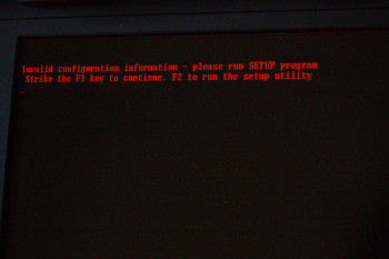
If the CMOS battery is empty, you will be prompted with the following error when you power on the machine.
Invalid configuration information - please run SETUP program
 Strike the F1 key to continue. F2 to run the setup utility
Please refer to instructions here:
How do I boot my T3200SX with an empty CMOS battery
SYMPTOM: How can I access the built-in BIOS ?
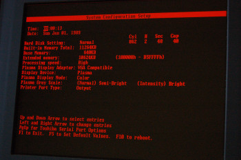
Press CTRL + SHIFT + F10 when the computer powers on. If this does not work, you may use the TEST3.EXE utility, a little program by Toshiba which will open up the BIOS settings from a DOS environment. You might want to include this utility in your computer recovery disk. See below for files that apply to this type of machine, or view all files at the files and resources section.
SYMPTOM: I am still unable to access the BIOS.
When the computer BIOS clock battery runs empty, it will clear all BIOS settings and will prompt you to review the system settings on power-up. This may be used to your advantage to get into BIOS. To force this behavior, disconnect the clock battery entirely. Wait for a few minutes and power up the computer again. The computer will ask the user to review the default settings. Please refer to How do I boot my T3200SX with an empty CMOS battery
SYMPTOM: My computer does not hold settings or time
You probably have an empty BIOS battery. The battery holds volatile information in a CMOS chip like information about your BIOS settings and system time. When the battery runs out, the information will be lost. You can still use your computer by going into BIOS settings and accepting the defaults (see above). See the troubleshooting section to replace your battery.
SYMPTOM: The computer turns on, power LED lights up, but I have no picture or a noisy picture
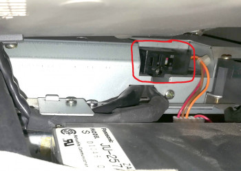
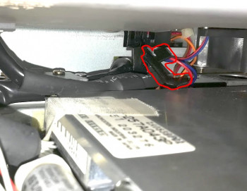
This could be caused by many things, but the most common issue is that the laptop lid open/close switch is just stuck in the on position. The switch, which is located under the cover, next to the floppy drive uses a rather low-quality plastic piece that latched with the screen hinge and is designed to detect when the lid is closed, and will cut the power to the display accordingly. It engages whenever the lid is closed, and since it is near the power supply, a plastic piece inside the switch may slowly deform over time and may get stuck inside the switch. The symptom you will see is a screen that will never seem to turn on when you open the lid, or will have a noisy picture, due to the switch stuck half-on. If you cannot repair the switch manually, the easiest workaround is to just disable it by removing the plastic piece entirely. This will make the screen then stay on regardless if the screen lid is open. Please see the gallery section for an image of the switch.
SYMPTOM: The computer doesn't turn on. When I flip the switch, the power light flashes briefly and then turns off.
Out of the three T3200SX's that I own, I've noticed two of them have started exhibiting this behavior. After investigating both computers, the issue was found in the power supply, specifically some of it's capacitors. I found, that four of the capacitors were leaking electrolyte and had failed (at the time failure, they were 36 years old parts, so I can't fault them!).
To fix this issue, you'll need to do some soldering on the power supply board. Word of caution: This is a somewhat dangerous procedure since the power supply can hold high voltages in its capacitors (while powered, over 200V DC for the plasma panel), so work on the power supply at your own risk!
To access the power supply, you'll need to disconnect and remove the Plasma display to get it out of the way. However, I have found an easier way that involves angling the plasma display and it's chassis top cover so that you have access, see the section under System Maintenance titled “How do I move the display out of the way”. The power supply is fastened to the chassis with five screws around the power supply (one screw in the middle is longer than the other four). Remove them, and disconnect the fan cable, plasma display lid sensor and power cable from the motherboard. When you have the power supply free, you can remove it's cover and access the circuit board. Again - a friendly reminder. Be careful around the bigger capacitors. They can hold a high voltage. I would recommend at least discharging the large HV capacitors close to the AC input line. Also the silk screening on the circuit board has a warning that heatsinks on the power supply may also be electrically charged.
The circuit board will be attached by two screws. After removing the screws, unplug the AC wire and the power supply fan wire, and you will be able to remove the board from the power supply case. You will see a group of four capacitors (1x 1000uf 25V, 3x 3300uF 10V) toward the middle-right hand side. Check both sides of the circuit board. If you notice electrolyte leakage on either side, you will have probably found the issue. Remove the old capacitors, clear the contamination with ethanol, or similar solvent, replace the capacitors and you should be back in business.
Parts list:
1: Radial capacitor, 1000uF 25V, 105'C
2: Radial capacitor, 3300uF 10V, 105'C
3: Radial capacitor, 3300uF 10V, 105'C
4: Radial capacitor, 3300uF 10V, 105'C
If this does not fix the issue, check the 5V and 12V pins on the motherboard if any of them have shorted to ground. If they have, you might have a shorted tantalum capacitor on the motherboard.
Q: What is the pinout and voltages of the cable going from the power supply to the motherboard?
A: The connector has 8 pins, and are as follows:
+--------+--------+--------+--------+--------+--------+--------+--------+
|  RED   |  RED   | BLACK  | BLACK  | ORNGE  | BLACK  | BROWN  |  BLUE  |
| +5V DC | +5V DC | Common | Common | +12V DC| Common | -5V DC | -12V DC|
+--------+--------+--------+--------+--------+--------+--------+--------+
SYMPTOM: Plasma screen is faded or does not show shades, even with the contrast knob turned all the way up
This might be an indicator that the capacitors on the display panel controller board have failed. Follow the steps under the heading “How can I access the internals of the display panel?” in the System Maintenance section to access the internals of the plasma panel.
Once you have removed the bezel, remove the four corner screws securing the display panel to the back cover of the display. Be careful removing the last two screws, as the fragile glass panel can fall off easily and be damaged. I recommend holding the panel while removing the final screw. Then disconnect the power, signal, and contrast adjustment connectors from the plasma panel assembly to remove it from the back cover.
Check the plasma controller board's capacitors for any leakage or evidence of grime. In one of my T3200SX computers I replaced the following capacitors on the board which resolved the issue. After removing the capacitors, only the 47uf 16V capacitors (C1, C9, C15) measured too low capacitance, but I went ahead and replaced all capacitors that appeared to have leaked electrolyte around them.
Parts list:
C1: Axial capacitor, 47uF 16V, 105'C
C6: Axial capacitor, 1uF 50V, 105'C
C7: Axial capacitor, 1uF 50V, 105'C
C9: Axial capacitor, 47uF 16V, 105'C
C10: Axial capacitor, 10uF 25V, 105'C
C15: Axial capacitor, 47uF 16V, 105'C
Note the grime around the failed black capacitors.
Q: What is the pinout and voltages of the cable going from the power supply to the plasma screen?
A: The connector has six positions, of which one is a key pin. The power cable has six wires. The green wire is attached directly to the plasma display frame as ground. The pinout and measured voltages are as follows:
+--------+--------+--------+--------+--------+--------+
|  BLUE  |  GRAY  |  KEY   | YELLOW |  RED   | BLACK  |
|-196V DC|-202V DC|        | +5V DC | +5V DC | Common |
+--------+--------+--------+--------+--------+--------+
Replacement BIOS ROM chips
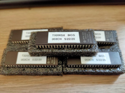 I have started selling replacement 003CH BIOS ROM chips for the T3200SX. If you're currently in need of upgrading your BIOS in order to install a different hard disk, you can use my BIOS chip to get around any limitations you may have with your current BIOS. The BIOS that I am selling is the the 003CH Hybrid BIOS, which is a combination of the 003C BIOS with the faster VGA BIOS of 003I. The hybrid BIOS will essentially act as an older BIOS and allow you to boot any hard disk. With this BIOS, all you need is a disk overlay program to correct the hard drive parameters. I can also program an XT-IDE enabled BIOS chip for you if you wish. Both chips are a drop-in replacement for the old BIOS chip, and should work great in any T3200SX system.
For more information, visit my BIOS ROM chips page.
Files
Documentation
| File | Size | Description |
|---|---|---|
| Toshiba T3200SX - Flyer.pdf | 8.0 MB | Toshiba T3200SX flyer with system specifications. |
| Toshiba T3200SX - Maintenance Manual.pdf | 3.7 MB | Toshiba T3200SX maintenance/service manual. |
| Toshiba - Accessory part list.pdf | 26 KB | Toshiba Accessory part list |
Community Guides
| File | Size | Description |
|---|---|---|
| Dumping and Copying Toshiba BIOS ROM | 1.9 MB | How to dump and copy your BIOS from a T3200SX This guide will walk you through the steps needed to dump and/or copy a BIOS ROM chip. This manual is especially helpful if you have a BIOS that doesn't accept custom hard drives, and you want to replace it with a version that does work with custom hard disks. Using the steps in this manual you can replace your BIOS with a BIOS version that allows you to use any hard drive in conjunction with the BIOS version found on this site (see download for t3200sx_bios_003ch.zip). An excellent guide written by High Treason. Note: This guide may apply to other models as well. Use guide at your discretion. You will need a TL866 EEPROM programmer. Highly recommended that you buy a second HN27C1024HG-85 ROM chip and keep your original unmodified and in a safe place. |
Operating System
| File | Size | Description |
|---|---|---|
| toshiba_dos_3_30.zip | 524 KB | Toshiba MS-DOS 3.30/R3C60SC bootable disk image |
Utilities
| File | Size | Description |
|---|---|---|
| tdiagsup_r3ce0.zip | 278 KB | Toshiba Diagnostics and Supplemental Diskette (R3CE0) for MS-DOS 3.30 |
| tdiagsup_dos50.zip | 278 KB | Toshiba Diagnostics and Supplemental Diskette for MS-DOS 5.0 |
| test3.zip | 21.1 KB | TEST3.EXE - Setup program for T3100, T3200, T5100 and T5200 series |
| xchad.zip | 5.3 KB | XCHAD.COM - Set Screen Attributes for T3200, T5100 series |
| HDDID.EXE | 1.6 KB | Identifies parameters of your IDE HDD |
| REBOOT.ZIP | 243 B | Performs cold boot with CTRL+ALT+DEL. |
| ANYDRIVE.ZIP | 13 KB | AnyDrive. This program overrides your BIOS HDD parameters so you can utilize up to 504 MB of a hard disk. It installs within the hard-drive's master boot record (MBR). Due to its very small footprint, this is recommended for Toshiba portables. To install, make a bootable floppy with AnyDrive, FDISK and FORMAT on it. Boot the floppy, install AnyDrive on your HDD, then boot from the HDD to activate Anydrive, but choose floppy boot once it prompts. Then partition with FDISK and run FORMAT to format new partitions. If you have a hard-drive that is larger than 512 MB, you can install AnyDrive by running the command “ANYDRIVE 0 1023 16 63”. This will utilize the first 512 megabytes on the disk. Please note that viruses may overwrite Anydrive in the MBR, so keep your favorite virus scanner and Anydrive handy on a bootable floppy. The reason you can only utilize 512 MB is because of the limitations in the BIOS CHS addressing scheme (1023 cyls, 16 heads, 63 sectors). For more information, see the included text file. |
| EZDRIVE9.ZIP | 423 KB | EZ-Drive 9.03W. This program overrides your BIOS HDD parameters so you can utilize up to a 8 GB hard disk. It installs within the hard-drive's master boot record (MBR). Requires 4 MB RAM to run. |
| View more files on this support site | ||
BIOS ROM dumps
| File | Size | System | Description |
|---|---|---|---|
| t3200sx_bios_003ch.zip | 47 KB | T3200SX | 003CH HYBRID BIOS. This Hybrid BIOS ROM has the BIOS from 003C, but the VGA-BIOS from 003I. This Hybrid BIOS will accept any disk installed and VGA graphics are accelerated. It contains the upgraded (and faster) 003I VGA-BIOS. You will only need an overlay program installed such as Anydrive to set/override the BIOS HDD parameters (see ANYDRIVE.ZIP in the Files section). Use a TL866 Minipro programmer or similar to program this on a compatible BIOS chip. Courtesy of High Treason. |
| t3200sx_bios_pack_1-0.zip | 312 KB | T3200SX | Custom Award BIOS ROM for the T3200SX which includes a patched version of XT-IDE ROM |
| t3200sx_bios_003c.zip | 46 KB | T3200SX | 003C BIOS ROM from my personal T3200SX. This BIOS version does not have a hard drive exclusion and will accept any hard disk regardless of it's part number. You will only need an overlay program installed such as Anydrive to set/override the BIOS HDD parameters (see ANYDRIVE.ZIP in the Files section). Use a TL866 Minipro programmer or similar to program this on a compatible BIOS chip. |
| t3200sx_bios_003e.zip | 402 KB | T3200SX | 003E BIOS ROM. This BIOS version will only accept Conner CP- series hard disks. Curiously this BIOS has the text “T3200SX V3.10 TOSHIBA [..] Copyright (C) 1985-1989 Phoenix Technologies Ltd.[..] FOR EVALUATION ONLY”. Courtesy of RemyV. |
| t3200sx_bios_003f.zip | 44 KB | T3200SX/120 | 003F BIOS ROM from a T3200SX/120 with a Conner 120MB HDD. This BIOS version will only accept Conner CP- series hard disks, and has preset options for 40 MB and 120 MB hard disks. |
| t3200sx_bios_003h.zip | 37 KB | T3200SX | 003H BIOS ROM. This BIOS version will only accept Conner hard disks. Courtesy of Milan Matijevic. Thank you! |
| t3200sx_bios_003i.zip | 36 KB | T3200SX | 003I BIOS ROM. The newest known BIOS version for the T3200SX. This BIOS version will only accept Conner hard disks. 003I has been improved with a quicker VGA BIOS than earlier versions. Courtesy of High Treason. |
Gallery
Links
Toshiba T3200SXC disassembly (identical to T3200SX) | Original URL
HighTreason's overview of the Toshiba T3200SX laptop with a in-depth look at the hardware
Vogons - Toshiba T3200SX BIOS Discussion
Baudband - Toshiba T3200SX
T3100 | T3100e | T3100SX | T3200 | T3200SX | T3200SXC | T5200 | T5200C
